CAD & 3D Parts Engineering Guide
A complete mechatronic design manual for the 3D printed and fabricated parts of the Skittles sorting robot. Covers fastener calibration standards, NEMA-17 stepper geometry, Design for Additive Manufacturing (DFAM), and step-by-step CAD breakdowns for every functional subassembly.
Threaded Fasteners & Heat-Set Inserts
3D printed plastics cannot reliably hold fine machine threads when screwed into directly—threads strip easily after 2–3 assembly cycles. This machine uses brass heat-set threaded inserts for all structural and motor-facing joints.
| Fastener Standard | Insert Pilot Hole ∅ | Pilot Depth | Standoff Outer ∅ (OD) | Through Clearance ∅ | Counterbore ∅ / Depth |
|---|---|---|---|---|---|
| M3 Brass Insert (M3×4.5mm) | 3.2 mm (0.32 cm) |
4.5 mm (0.45 cm) |
6.5 mm (min 1.65mm wall) |
3.2–3.4 mm (close/free fit) |
6.0 mm ∅ / 3.2 mm depth (for M3 cap screw) |
| M2.5 Brass Insert (M2.5×4.0mm) | 2.8 mm (0.28 cm) |
3.8 mm (0.38 cm) |
5.5 mm (min 1.35mm wall) |
2.7–2.9 mm |
5.0 mm ∅ / 2.6 mm depth |
| M4 Extrusion / Frame Bolt | Direct tap / T-nut | Through-hole | 10.0–12.0 mm boss |
4.3–4.5 mm clearance |
7.5 mm ∅ / 4.2 mm depth |
Heat-Set Practice Coupon & Slicer Wall Enforcement
Before installing inserts into large structural parts (like base.stl or plate_stepper.stl), students should print a small 10-minute calibration coupon ($40\times20\times8\,\text{mm}$) containing three test holes ($\varnothing 3.0\,\text{mm}$, $\varnothing 3.2\,\text{mm}$, and $\varnothing 3.4\,\text{mm}$).
- Slicer Perimeter Walls: Enforce 4 solid perimeter walls (min 1.6mm thickness) in your slicer around all screw bosses. If printed with only 2 walls, the brass insert will crush the infill and blow out the outer wall under torque.
- Soldering Iron Temperature: Set soldering station to exactly $260^\circ\text{C}$ for PLA ($280^\circ\text{C}$ for PETG). Higher temperatures char the plastic into brittle carbon residue.
- Dwell Time & Quench: Apply gentle downward pressure for $2\text{–}3\text{ seconds}$ until the top flange sits flush with the surface. Remove the iron tip immediately and allow $15\text{ seconds}$ to solidify before threading in an M3 bolt.
NEMA-17 Stepper Motors & 5mm D-Shafts
Both the inspector wheel and the sorting slide are driven directly by NEMA-17 stepper motors. Proper mechanical interface requires precise alignment to the motor's center pilot boss and zero-slip shaft couplings.
NEMA-17 Mounting Pattern
The motor flange has four M3 threaded holes on a 31.0 mm square bolt circle with a raised cylindrical registration boss.
- Center Pilot Boss:
22.0 mmdiameter ×2.0 mmheight. Model the mating pocket at22.6–22.8 mm(0.3–0.4mm radial clearance). - Hole Pitch:
31.0 mm × 31.0 mmsquare. - Clearance Slots: Model mounting holes as
3.4 mm × 8.0 mmstadium slots to allow belt or gear engagement adjustment.
5.0 mm D-Shaft Positive Coupling
Standard NEMA-17 shafts have a 5.0 mm outer diameter with a machined flat.
- Shaft Bore:
5.15 mm(0.15mm total clearance for slip fit). - Flat Offset: Flat edge at
4.5 mmdiameter (0.5 mm cut depth). - Grub Screw Set: Radial M3 heat-set insert hole perpendicular to the D-flat. The grub screw clamps firmly onto the flat surface, preventing angular slip.
- Collar Wall: Minimum
3.5 mmcollar radial thickness around the bore.
Kinematic Homing & Rotary Cam Lobe Design (`cam.stl`)
Why does an automated sorting machine need a homing switch, and why is it shaped like an eccentric rotary cam instead of a hard mechanical stop?
1. Why Homing is Mandatory (Open-Loop Actuators)
Stepper motors and continuous-rotation actuators execute relative step pulses (e.g., 50 steps = 90°), but they possess zero absolute position memory:
- Boot State Uncertainty: When powered on, the Pi cannot know if Pocket #1 is under the sensor, under the chute, or at a random 37° angle.
- Cumulative Step Drift: Over thousands of candy indexing moves, micro-slips or inertia spikes can cause small step loss. Without periodic homing, the nests drift out of alignment with the optical shroud.
- The Physical Datum ($0.00^\circ$): The limit switch provides an absolute, unchangeable electrical ground truth.
2. Why a Cam Lobe (`cam.stl`) vs. Hard Stops
In linear mechanisms (like 3D printers), a carriage hits an endstop at the end of travel. But in a rotary candy sorter:
- Continuous Unidirectional Flow: The wheel must rotate forward 360° continuously. A hard pin would block rotation, forcing the motor to reverse 360° every cycle.
- Impact & Fatigue Elimination: Hitting a hard stop shocks the motor shaft, skips steps violently, and fractures 3D-printed brackets.
- Smooth Tangential Ramp: The eccentric cam lobe provides a gentle 25° incline that pushes the microswitch roller smoothly without impact or bounce.
cam.stl in Fusion 360
When modeling the homing cam in Fusion 360:
r_base = 12.0 mm(Base cylinder radius — clears switch roller by 1.5mm).lobe_lift = 3.5 mm(Radial rise — sufficient to fully depress switch arm with 1.2mm overtravel safety margin).rise_angle = 25.0 deg(Smooth tangent ramp with $R=4.0\text{mm}$ blend fillets to eliminate impact shock).hub_bore = 5.15 mm(D-shaft bore with $4.5\text{mm}$ flat and M3 heat-set insert grub screw clamp).
Design for Additive Manufacturing (DFAM)
FDM 3D printing builds parts layer by layer. Designing functional mechanical components requires accounting for anisotropic layer strength, overhang limits, thermal creep, and slicer toolpaths.
1. Layer Orientation vs. Mechanical Shear
3D printed parts have ~60% lower tensile strength across the Z-axis (inter-layer adhesion) than along the X-Y print plane.
- Motor Shafts & Hubs: Print shafts vertically so rotational torque stresses the strong X-Y continuous perimeters, not the layer bonds.
- Mounting Ears & Brackets: Orient so screw clamping forces compress layer lines together rather than pulling them apart in tension.
2. Overhangs, Chamfers & Horizontal Holes
FDM cannot extrude plastic into empty air without supports.
- The 45° Overhang Rule: Slopes up to 45° from vertical print cleanly without support structures.
- Teardrop Holes: Horizontal circular holes larger than 6mm sag at the top apex. Model horizontal holes with a 45° peaked "teardrop" or diamond profile.
- Base Chamfers: Add a 0.5mm × 45° chamfer to the bottom edge of parts to eliminate the "elephant's foot" brim squish.
3. Wall Thickness > Infill Percentage
Mechanical rigidity is determined primarily by the outer perimeters (shells), not the internal infill.
- For structural brackets (`plate_stepper`, `base_for_slide`): Use 4 perimeters / walls (1.6–2.0mm solid perimeter) and 25–30% Gyroid infill.
- Adding walls increases torsion and bending resistance by 250% compared to just increasing infill from 20% to 80%.
4. Material Matrix: PLA vs. PETG
Select filament based on operating environment and thermal exposure.
- PLA: High tensile stiffness, low thermal shrinkage (±0.1mm accuracy), easy bridging. Perfect for the
wheel.stl,inspection.stloptical darkroom, and chassis panels. - PETG: Higher heat deflection temp (75°C vs PLA's 52°C) and impact ductility. Mandatory for
plate_stepper.stl(stepper motor bodies frequently reach 50–60°C during continuous operation).
The 4 Core Subassemblies in 3D Files/
Deconstructing the engineering intent, critical dimensions, and assembly interfaces of the actual project files.
Subsystem 1: Chassis, Motor Mounts & Electronics Enclosures
Key Files: plate_stepper.stl, plate_stepper_new.stl, plate_zero_v2.stl, Case_Zero.stl, screen_holder.stl, stand.stl
- Stepper Plate: Mounts the NEMA-17 stepper to 2020 aluminium extrusion. Uses slotted M4 clearance holes for tension adjustment and an M3 heat-set standoff array for the limit switch.
- Raspberry Pi Zero 2 W Carrier: Standoff pattern matches Pi Zero mounting holes (
58.0 mm × 23.0 mmpitch with M2.5 inserts). Elevated 4mm above the plate to allow ventilation and prevent shorting against conductive frames. - TFT Bonnet Screen Bezel (`screen_holder.stl`): Angled 30° upward toward the operator for ergonomic visibility. Includes clearance channels for the 40-pin ribbon cable breakout.
Subsystem 2: The Inspector Subassembly (Wheel, Cam & Optical Darkroom)
Key Files: wheel.stl, cup_holder.stl, cam.stl, inspection.stl, rgb_holder.stl, light_1.stl
- Parametric Nest Pockets: Sized for standard candy dimensions (
∅ 13.5 mm × 7.0 mm depth) with a7° draft angleto prevent wedging during gravity ejection. - Retaining Ring Lip: A 1.2mm circumferential lip retains the Skittle against centrifugal displacement during high-speed 90° indexing moves.
- Optical Isolation Darkroom (`inspection.stl`): The AS7341 spectral sensor requires absolute control over photon illumination. Ambient light bleeding from room lamps or windows skews spectral ratios. The printed darkroom hood shrouds the sensor at a calibrated 8.0 mm focal distance directly above the candy nest, with interior light-trap baffles to eliminate internal reflections.
- Homing Cam (`cam.stl`): Radial eccentric lobe designed to depress the VMA327 limit switch roller smoothly over 15° of rotation without bounce.
Subsystem 3: Kinematic Sorting Slide & Distribution Chute
Key Files: slide_v1.stl, base_for_slide.stl, Needle.stl, Needle_45.stl, dial_indicator.stl, cup_holder.stl, cup_plate.stl
- Gravity Slide Angle: The chute slope is set to 32° from horizontal. Candy sugar coatings have a static friction coefficient of μ ≈ 0.45 against smooth PLA; a 32° pitch guarantees rapid candy acceleration (>0.5g) without stalling.
- Curved Transition Radius: The candy entry throat uses a 12mm fillet radius to smoothly redirect vertical drops from the wheel into horizontal radial flow.
- Rotational Inertia Minimization: The chute's wall thickness is optimized to 1.6mm (4 perimeters) with hollow ribbing to keep rotational mass low, allowing the NEMA-17 stepper to accelerate at
2000 rad/s²between bucket positions without missing steps.
Subsystem 4: Anti-Jam Feeder Hopper & Oscillating Agitator
Key Files: feeder_body.stl, cone.stl, agitator.stl, the_middle_maker.stl, stopper.stl, top_closure.stl
- Particulate Bridging & Hopper Geometry: Bulk Skittles jam when hopper funnel walls are too shallow (<50°), creating structural candy arches (bridging). The hopper cone is modeled with steep 65° funnel walls.
- Singulation Throat: The exit aperture narrows to
15.0 mm × 10.0 mm—wide enough for exactly one Skittle to pass flat, but physically too narrow for two Skittles to enter side-by-side. - Cam-Driven Agitator Paddle (`agitator.stl`): Oscillates with each rotation cycle to break nascent particulate arches at the funnel base and maintain continuous single-file feed flow into the wheel nests.
Parametric Modeling Master Table in Fusion 360
Never hardcode numbers into sketches. Set up a global User Parameters Table (Modify → Change Parameters) before sketching any geometry.
| Parameter Name | Expression | Value | Design Purpose |
|---|---|---|---|
d_shaft |
5.0 mm |
5.0 mm | NEMA-17 motor shaft nominal diameter |
clearance_fit |
0.2 mm |
0.2 mm | Standard 3D print sliding tolerance margin |
m3_insert_pilot |
3.2 mm |
3.2 mm | Pilot hole diameter for M3 heat-set inserts |
m3_clearance |
3.4 mm |
3.4 mm | Free through-hole for M3 bolts |
wall_thick |
3.0 mm |
3.0 mm | Nominal structural shell wall thickness |
skittle_diam |
13.5 mm |
13.5 mm | Caliper-measured maximum candy diameter |
skittle_thick |
7.0 mm |
7.0 mm | Caliper-measured maximum candy thickness |
n_pockets |
4 |
4 | Number of indexing pockets on inspector wheel |
chute_angle |
32 deg |
32° | Gravity slope angle of sorting chute |
full_design.f3z):
- Ground the primary base plate (Right click → Ground) so it cannot move in 3D space.
- Create Revolute Joints between the NEMA-17 motor shafts and the `wheel.stl` and `slide_v1.stl` hubs.
- Use Motion Links (Assemble → Motion Link) to link stepper rotation to cam switch actuation.
- Run Inspect → Interference between the rotating wheel and the stationary optical shroud before sending parts to the 3D printer.
3D Parts Catalog & Interactive STL Inspector
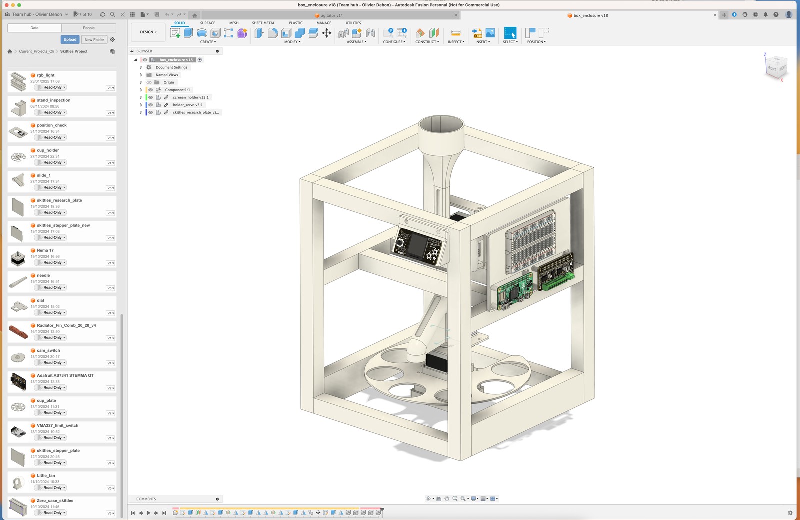
Explore the physical geometries of all 16 core STL files in the project. Drag and drop any .stl file from the 3D Files/ folder directly into the WebGL inspector below to orbit, zoom, inspect internal bores, and check slicing orientation.
Core 3D Printed Part Breakdown (Exact CAD Models)
1. Inspector Wheel
180 KB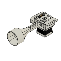
File: 3D Files/wheel.stl
4-pocket indexing wheel with 7° draft nests and outer retaining lip. Mounts directly to NEMA-17 D-shaft.
- Filament: PLA (Black recommended for optical isolation)
- Settings: 3 walls, 20% Gyroid infill, 0.2mm layer height
- Hardware: M3×4.5mm insert + M3×6mm set screw
2. Optical Darkroom Chamber
341 KB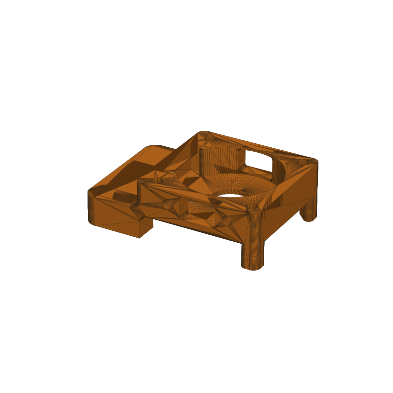
File: 3D Files/inspection.stl
Darkroom hood holding the AS7341 spectral sensor at 8mm calibrated focal height with ambient light-trap baffles.
- Filament: Matte Black PLA (prevents internal reflections)
- Settings: 4 walls, 25% infill, 0.16mm layer height
- Hardware: 2× M2.5 brass heat-set inserts
3. Kinematic Sorting Slide
1.1 MB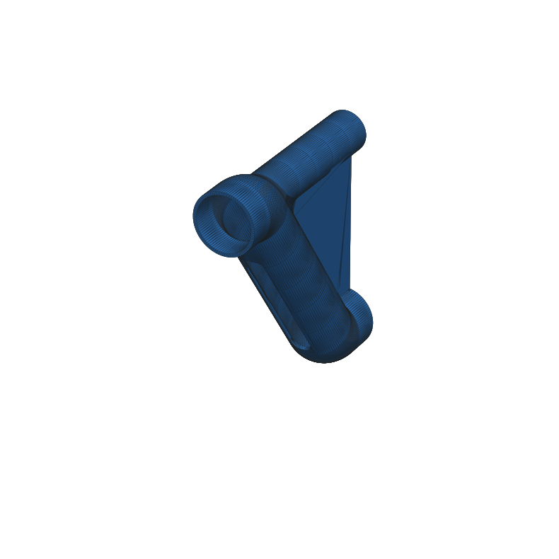
File: 3D Files/slide_v1.stl
32° low-friction gravity slide with 16mm U-channel to guide sorted Skittles to 5 radial bucket targets.
- Filament: PLA (Sanded or polished inner chute)
- Settings: 4 walls, 20% infill, 0.2mm layer height
- Hardware: M3×4.5mm insert + M3 grub screw
4. Anti-Bridge Hopper Cone
2.5 MB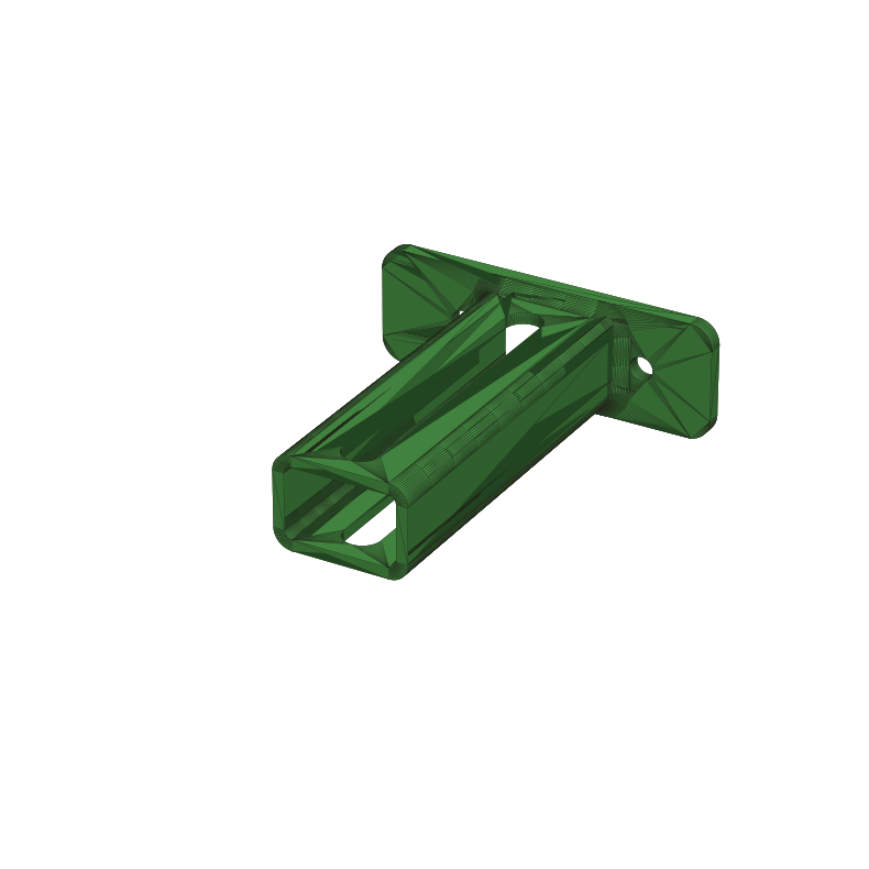
File: 3D Files/cone.stl & feeder_body.stl
Steep 68° funnel walls to prevent particulate candy bridging and guide bulk Skittles into the singulation throat.
- Filament: PLA or PETG
- Settings: 3 walls, 20% infill, 0.2mm layer height
- Interface: Mating flange for
the_middle_maker.stl
5. Oscillating Agitator Paddle
13 KB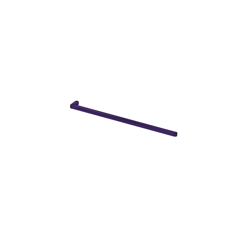
File: 3D Files/agitator.stl
Sweeping paddle that agitates bulk candy at the funnel throat to break arches and maintain continuous flow.
- Filament: PETG (High fatigue cycle resistance)
- Settings: 100% solid infill (small 13KB part)
- Clearance: 2.0mm clearance against funnel throat
6. Stepper & Switch Mount Plate
463 KB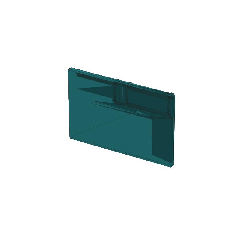
File: 3D Files/plate_stepper.stl
Structural plate mounting NEMA-17 to frame with 6mm slotted travel and M3 heat-set limit switch standoffs.
- Filament: PETG (Required for 50°C motor heat resistance)
- Settings: 4 walls, 30% Gyroid infill, 0.2mm layer height
- Hardware: 4× M3 motor bolts + 2× M3 switch inserts
7. Radial Homing Cam
84 KB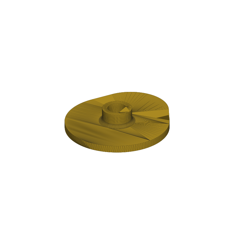
File: 3D Files/cam.stl
Eccentric rotary cam with +3.5mm lobe lift to smoothly actuate the limit switch without mechanical shock.
- Filament: PLA or PETG
- Settings: 4 walls, 100% solid infill, 0.16mm layer height
- Hardware: M3×4.5mm insert + M3 set screw for D-flat